Benchtop Power Supply
Testing and troubleshooting electronics projects can be difficult without a proper power supply available. Most microcontrollers can be powered through my desktop PC using USB which is great for quickly adjusting code or testing the entire project as I can use serial monitors and other indicators to generate precise data. However, testing individual components and troubleshooting sub-assemblies is both cumbersome and time-consuming using this method. A variable benchtop power supply solves these issues and gives me access to quick power at exactly the voltages I need so I can test components and sub-assemblies without having to plug into my PC, start up the IDE, connect everything to the microcontrollers, and write a sketch targeting that component.
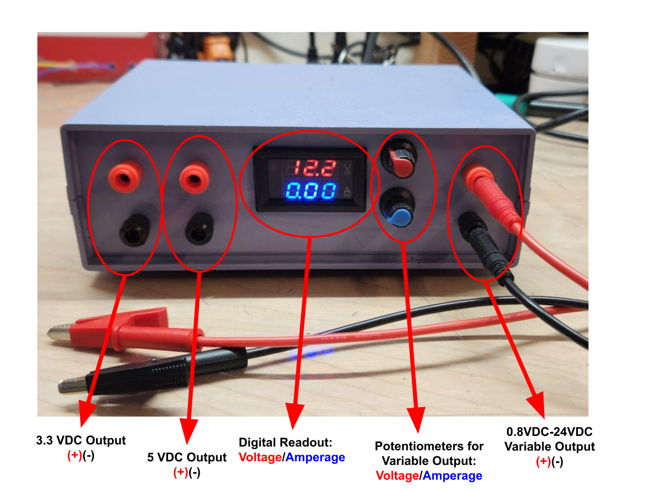
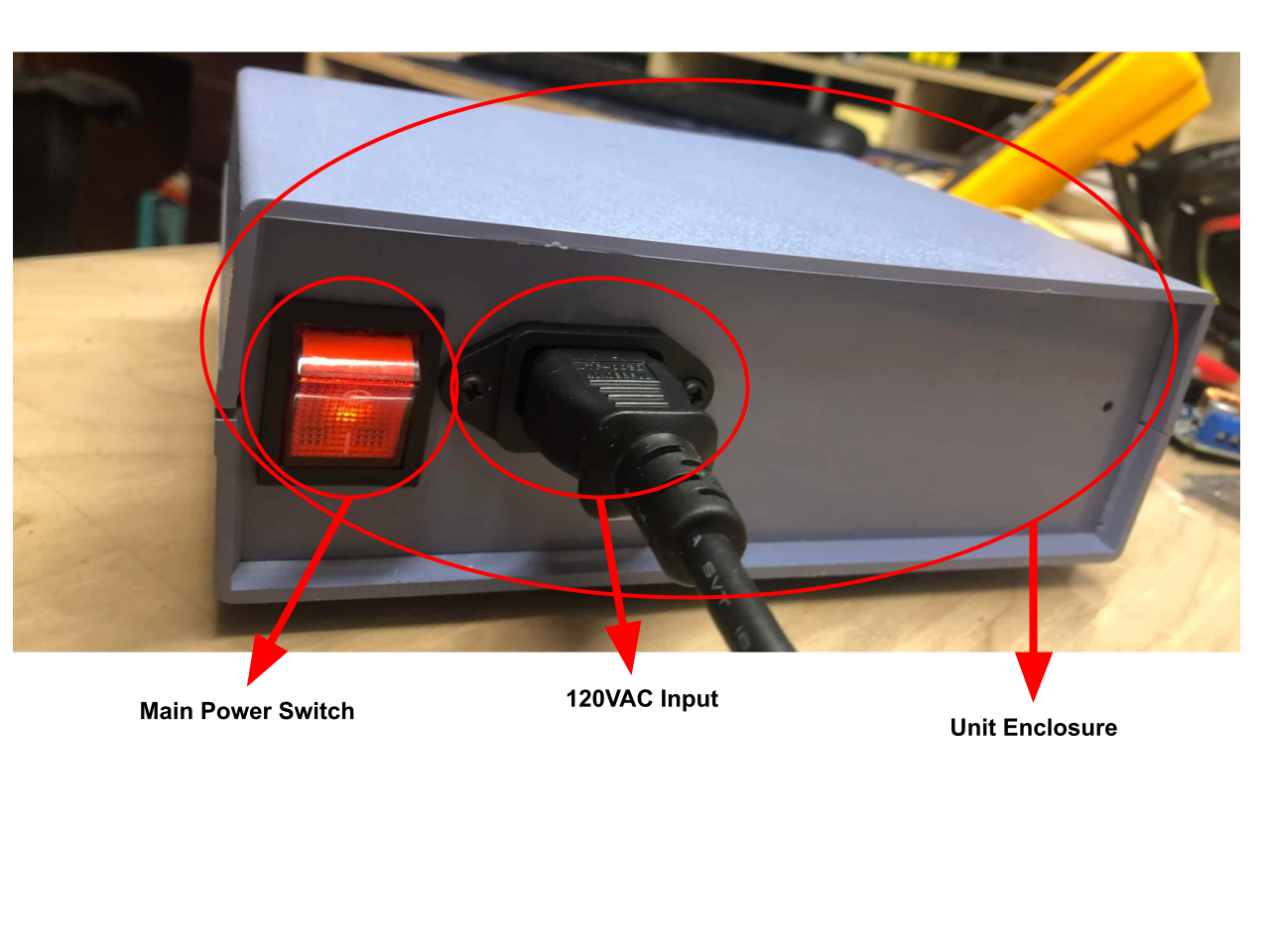
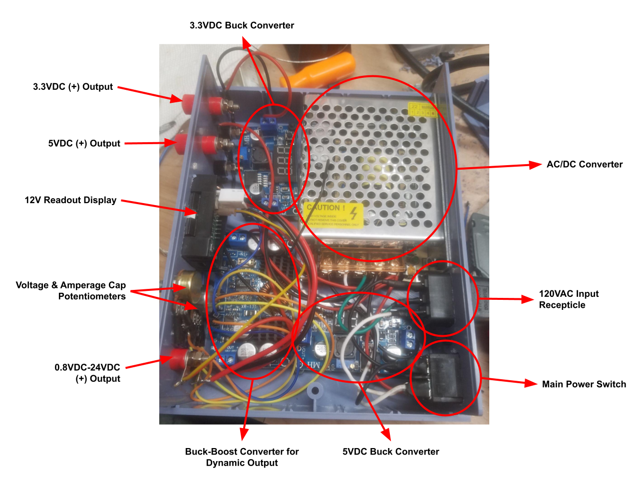
Final Design: Input: 120VAC with main power switch in rear of enclosure | Outputs: 3.3VDC static, 5VDC static, 0.8VDC-24VDC dynamic | Static Outputs: Convert 120VAC to 12VDC using an AC/DC buck converter. Route 12VDC to two buck converters for static outputs (3.3VDC & 5VDC), adjust integrated potentiometers to set static voltages and connect board outputs to (+) and (-) output banana jacks. | Dynamic Output: Convert 120VAC to 12VDC using an AC/DC buck converter. Route 12VDC to main buck-boost converter (Low: 0.8VDC, High: ~29VDC). Unsolder integrated potentiometers to connect board to outboard “finger” potentiometers. These control both the dynamic voltage output and the amperage cap. Route 12VDC to display. Connect board outputs to (+) and (-) output banana jacks.

Features:
3.3VDC static output
5VDC static output
0.8VDC-24VDC dynamic output (controlled by outboard potentiometer)
5A fuse in AC/DC converter for overcurrent protection
Amperage cap for protecting sensitive electronics (controlled by outboard potentiometer)
2.5” profile for easy storage (7.5”W x 6”D)
Banana jack outputs enable diverse connection selection